|
|
Requirement 2: Takeoff Field Length (TOFL) |
JAR 25.109 Accelerate-stop distance.
(a) The accelerate-stop distance (...) is the greater of the following distances:
(2) The sum of the distances necessary to -
(i) Accelerate the aeroplane from a standing start to V1 and continue the acceleration for 2·0 seconds
after V1 is reached with all engines operating; and
(ii) Come to a full stop from the point reached at the end of the acceleration
period prescribed in sub-paragraph (a)(2)(i) of this paragraph, assuming that the pilot
does not apply any means of retarding the aeroplane until that point is
reached and that all engines are still operating.
JAR 25.111 Take-off path.
(a) ...
(2) The aeroplane must be accelerated on the ground to VEF, at which point the critical
engine must be made inoperative and remain inoperative for the rest of the take-off; and
(3) After reaching VEF, the aeroplane must be accelerated to V2.
(b) During the acceleration to speed V2, the nose gear may be raised off the ground at a
speed not less than VR. However, landing gear retraction may not be begun until
the aeroplane is airborne.
(c) During the take-off path determination in accordance with sub-paragraphs
(a) and (b) of this paragraph -
(2) The aeroplane must reach V2 before it is 35 ft above the take-off surface ... .
JAR 25.113 Take-off distance and take-off run
(a) Take-off distance is the greater of -
(1) The horizontal distance along the take-off path from the start of the take-off to the point
at which the aeroplane is 35 ft above the take-off surface, determined under JAR 25.111; or
(2) 115% of the horizontal distance along the take-off path, with all engines operating,
from the start of the take-off to the point at which the aeroplane is 35 ft above the take-off
surface, as determined by a procedure consistent with JAR 25.111.
|
|
The takeoff field length consists of two parts: takeoff ground roll and takeoff path to 35 ft height.
The equation for takeoff ground roll is:
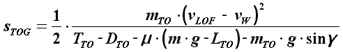
The ground roll distance depends on several measures:
|
|
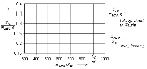
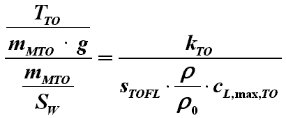
The wing loading of the aircraft has to be to the left of the red line in order to fulfil the takeoff requirement. (Bear in mind: The thrust has to increase if the weight increases.)
| Aircraft | Airbus A300-600B | A310-300 | A340-300 | Antonov AN124 | Boeing B737-600 | B777 | Learjet 60 | McDonnell Douglas MD11 | Tupolev TU204 |
|---|---|---|---|---|---|---|---|---|---|
| TO- thrust / weight wing loading [m²/kg] |
0.000485 - 0.00051 | 0.000424 - 0.00052 | 0.000311 - 0.000339 | 0.000358 | 0.000589 | 0.000515 - 0.000536 | 0.000902 | 0.000371 - 0.000383 | 0.000658 - 0.000797 |