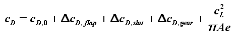
|
|
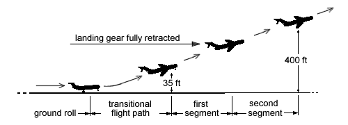
Requirement 3: Second Segment Climb |
JAR 25.121 Climb: One-engine-inoperative.
(b) Take-off; landing gear retracted. In the take-off configuration existing
at the point of the flight path at which the landing gear is fully retracted,
and in the configuration used in JAR 25.111 but without ground effect, the
steady gradient of climb may not be less than
2·4 percent
for two-engined aeroplanes,
2·7 percent for three-engined aeroplanes, and
3·0 percent for four-engined aeroplanes,
at V2 and with -
(1) The critical engine inoperative, the remaining engines at the take-off
power or thrust available at the time the landing gear is fully retracted,
determined under JAR 25.111, unless there is a more critical power operating
condition existing later along the flight path but before the point where the
aeroplane reaches a height of 400 ft above the take-off surface(...); and
(2) The weight equal to the weight existing when the aeroplane's landing
gear is fully retracted, determined under JAR 25.111.
In figure 1 the second segment while the takeoff is presented according to JAR.
|
|
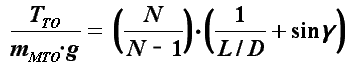
The second segment is based on the situation with one engine of the aircraft inoperative.
Therefore, the thrust of the remaining engine(s) has to be enough to climb as required.
From the equilibrium condition can be got two equations:
![]()
![]()
Since these equilibrium conditions have to be achieved with one engine inoperative, the required thrust at takeoff with all engines operating has to be higher by a factor N/(N-1). N is the number of engines. The thrust to weight ratio following from the requirement is:
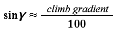
The climb gradient ![]() in the equation above is small. Therefore it can be simplified:
in the equation above is small. Therefore it can be simplified:
|
|
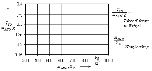
The takeoff thrust to weight ratio of the aircraft must be above the green line to fulfil the requirement for the second segment condition. (Bear in mind: Thrust means climb rate.)
| Aircraft | Airbus A 300-600B | Airbus A 310-300 | Airbus A 340-300 | Antonov AN 124 | Boeing B 737-600 | Boeing B 777 | McDonnell Douglas MD11 | Tupolev TU 204 |
|---|---|---|---|---|---|---|---|---|
| Takeoff thrust Takeoff weight [ - ] |
0.308 - 0.324 | 0.290 - 0.356 | 0.220 - 0.240 | 0.231 | 0.307 | 0.292 - 0.304 | 0.299 - 0.309 | 0.341 - 0.413 |